Kit Assembly Notes

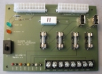
It is assumed you know how to solder. Refer to the photo for component placement. Please read through all the notes before you start assembly.
To allow this PCB to carry larger amounts of current, the traces are very wide and the via thermals have oversized spokes. Because of this, it *may* take more heat than you expect to get solder flowing... but as when soldering anything, be careful not to overheat the PCB, components, etc. I find using flux helps in some cases.
Install each part so it is within the white part outline.
All holes are plated, so soldering one side is sufficient. You can solder both the top and bottom board sides if you wish.
When installing the ATX connectors, if you wish to substitute an ATX12 connector, see the ATX/Dell Wiring page for guidance as to how to orient the connector - you may need to modify the connector keys, etc.
When installing the colored testpoint loops, I like to use this color scheme: GND=black, 5V=red, 3.3V=orange, +12V=yellow, -12V=white.
When installing the LEDs, D1 is green, D2 is orange. LEDs are diodes (i.e. they must be installed in the correct orientation or they won't ever light up.) The longer lead on the LED goes to the square pad on the PCB bottom.
When installing the R1 and R2 resistors, R1 is 237 ohms (red orange violet black), R2 is 1K ohms (brown black red) Check this resistor color code table for additional info.
R4-R7 are not included in a kit (or a fully assembled board.) These pads are provided should you wish to experiment with the D+/D- lines on USB2. Some devices require these lines to be held at certain voltages when used to charge them - one specific example is the iPad. Refer to the ATX PS Adapter schematics for more details.
Install the fuses after soldering the fuseholders into F1-F4. All four fuses are the same.
Lastly, stick the four round rubber pads on the bottom of the board in the corners.
Test the board by plugging in an ATX PC Power Supply (be sure you are using the correct 20 pin connector for the type of supply you have.) With the switch off, the orange standby LED should light when the PC supply is plugged into the wall. With the switch in the on position, both the green and orange LEDs should light and the power terminals should be live. Probe each terminal with reference to ground to check that it is close to the labeled voltage (you generally will get whatever your PC supply puts out.)